How To Wire A 5 Pin Relay Diagram
In simple words, a relay is an electromagnetic switch, which we mostly used to switch the power supply automatically or manually. In this post, I am sharing a simple 5 pin relay wiring diagram. Relay is available in different shapes and types. it's can be according to the pins, or contacts, ampers, voltage ratting (AC or DC). These contacts are pin can 4, 5, 8, 11, 14, etc. But in all pins, we have two for the coil. Where we provide the required ratting current. For example, if we have a 12-volt DCV relay. So we will provide the 12 volts DC (Direct current) to the relay coil. And if we have the 220 ACV then we provide the 220 volts AC (alternating current) to relay coil.
The other pin or contacts called main contacts or switching contacts. In the relay switching pins are contains- common, NC (normally open), NO (normally close).
5 Pin Relay Wiring Diagram
A pin relay is SPDT relay, which means that the contacts of relay single pole double throw. In single pole double throw relay, we have one pin is common, 2nd are normally close and 3rd are normally open. Two pins for the coil. This relay can be used for different types of controlling or switching. Such as for lights, fan, fuel pump, etc. Here I showed the 5 pin relay diagram.

In the above diagram, I have shown a single pole double throw relay (5 pin relay). Not that his relay can be 5 volts DCV, 12 volts DCV, 24 Volts DCV, etc according to ratting voltage of coil. in the above 5 pin relay diagram 1 and 2 pins for coil, 3 is the common pin, 4 is normally close and 5 is normally open pin.
How To Use 5 Pin Relay
A relay can be used for different switching. Do control electrical devices automatically then the relay is the best option. When we talk about the relay, as I already told you that there are different types of the relay, for different works. But this post is about the 5 pin relay. As I showed in the 5 pin relay diagram. this contains 3 main pins. As a single pole double throw have.
So when we talk about single pole double throw, it means that it has a common point, and two other points (NC and NO).
So if want to switch something from a single pole double throw relay, you need to use the common and other points. For example, if you need that switch off the light bulb when the relay operates. Then you need to use a common and normally close pin. And if want to switch on the light bulb then you need to use the common and normally open pin. Here I have shown how to wire 5 pin relay for lights.
5 Pin Relay Wiring Diagram for lights
In the below wiring diagram, I have shown how to switch on lights when the relay operates, and how to switch off when the relay operates.

Same you can also use this relay for the fan, if you want to control or wire a fan with a relay you can follow the same method. Note that you must provide the ratted voltage to the relay coil. If your relay is 12 volts DCV. Then you mush provide the 12 volts DCV.
How To Use Relay
The relay mostly used for switching electronic devices in electronic circuits. The relay has contacts in which main contacts are used to switches the circuit and contacts for the coil. A relay has a different trigger voltage, the trigger voltage is the voltage in which relay coil operation works and change normally close to open and normally open with close circuit.
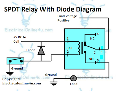
The trigger voltage can be different like 3v, 5v, 12v, 24v, etc. our below diagram "relay" trigger voltage is 5 volts. In the below diagram, I have shown a relay that switches the load. The +5 volts is provided to the relay coil and the ground is connected through a switch. (A switch can be a transistor or a microcontroller which performs the switching operation). A diode is connected across the relay coil, this diode is called the Fly back diode. The purpose of the diode is to protect the transistor or microcontroller from a high voltage spike that can be produced by the relay coil.

In the above single pole double through with fly back diode diagram, I have shown ground is connected directly to load, and a positive voltage is connected to common pin of relay and supply is goes through the normally open contacts. When relay operates the common and NO will make a close circuit and positive supply is starts flowing to load.
Source: https://www.electricalonline4u.com/2020/11/5-pin-relay-wiring-diagram-use-of-relay.html
Posted by: barbarayoullifeireoau.blogspot.com
Posting Komentar untuk "How To Wire A 5 Pin Relay Diagram"